1.1) Description
What is it?
Why did we develop it?
Who needs it?
How does it work?
How is the test performed?
1.2) Explaining the frame/field timing notation
Common example
Y/C split example
1) Introduction
As part of the project "Österreich am Wort", the Österreichische Mediathek (National Audiovisual Archive of Austria) had a complete long-term digital video archiving system developed, which includes capturing, analyzing, describing, documenting and storing video recordings that originate from a variety of tape-based formats and systems. This system is called "DVA Profession" and was originally published at the end of July 2011.
Primary, in order to consolidate our signal handling, we took a very critical look at the output video files created by us and found incidents of strange behavior regarding the fields of a video signal. A complex, time consuming and mainly manual analysis of one of our recordings revealed faulty processing done by a newly installed video A/D converter.
While we were waiting for a firmware update that had been promised to us as a result of our bug report, we searched for an automated way to discover discrepancies in the order of fields. Due to the lack of existing solutions we developed a tool that showed to be a very powerful option for analyzing the digital signal chain.
The result is the "DVA Profession Fidelity Analyzer" - or "DVA Fidelity" for short.
1.1) Description
What is it?
"DVA Fidelity" is a method mainly designed to automatically find frame/field timing issues in a video signal chain resulting in a digital video file.
It consists of 3 parts:- A specially crafted test-video
- A corresponding evaluation tool
- Analysis results as plain text file
Conventional test-videos are only designed for checking image quality, but cannot be used to analyze any time-based behavior that requires monitoring data over a certain time period. This is, for example, necessary to examine frame/field timing handling. Our signal analysis must not be mistaken with analyzing an analogue video signal on a voltage level (e.g. using an oscilloscope), as DVA Fidelity only verifies whole images - not lines, signal voltages or sync-tips, etc.
What we call "frame/field timing issues", are incidents where a whole frame and/or field at a certain time position in an output video does not contain the expected field/frame information from the source video at the right time index. Typical examples would be "dropped frame/field", "duplicated frame/field", etc.
When testing for frame/field timing issues, it is necessary to know that timing corrections are not always caused by faulty devices. In some cases they are normal: Whenever video equipment is connected to each other, each is running with its own timer. In case there is no ability for them to be synchronized by clocking mechanisms, it is clear that sooner or later those timers will drift apart, requiring runtime corrections to be made to the video signal. However, even though these timing corrections are necessary, each equipment handles these corrections differently.
So "DVA Fidelity" is a way of detecting and visualizing any intervention in the original video signal, and therefore provides a way of comparing timing-handling methods of different equipment to each other.
Why did we develop it?
As a matter of fact we stumbled over frame/field timing issues with our high quality video A/D converter equipment, causing fields to show up in wrong frames. This negative effect introduced by the A/D converter lasts over a time period of several minutes and impairs the resulting video recording, making it unsuitable as long-term archival copy as well as possibly impeding its quality when transcoding the video in the future.
After reporting our results to the vendor of the A/D converter we were promised a possible fix in a future firmware update. In order to provide feedback to the developers as soon as possible it became necessary to find a way of verifying the functionality after applying the new firmware. It seemed that there were no existing options for performing this kind of signal analysis in videos, which required us to find a way to verify the reliablity of equipment ourselves. First, mainly manual evaluations quickly revealed the need for an impartial testing scenario which could be conducted and reproduced in reasonable time. The contentual requirements of a suitable testvideo as well as the algorithm for automating the detection were developed based on findings made during the manual analysis phase.
As mentioned above, timing issues introduced by a video signal chain not only lead to quality degradation but might also impede future actions applied to the video material. As in our case the wrongly interleaved fields do not only look bad on progressive displays (e.g. TFTs), but it would also have tremendously negative visual effects in case of, for example, applying deinterlacing filters. Since the development of DVA Fidelity we have run more than hundred hours of our specially developed test-video through a variety of video equipment and have figured out that it is not only useful for finding errors but also to verify the correct functionality of signal chains, as well as getting an idea about timing corrections introduced on the way.
Who needs it?
-
Anyone working with digital video for whom high quality of video signals is important:
DVA Fidelity offers the possibility to detect all kinds of changes in the field order, which differ from the source. Thus, for example, the output and/or configurations of video A/D converters can be compared.
-
Professional organizations dealing with equipment, applications and signals necessary for handling digital video
(A/D converters, transcoding software, SDI-to-SDI connections, etc…)Dealing with high quality video requires knowledge about the effects that happen in the used environment. Timing handling on frame/field level is one of the less discussed issues. Even though it can be of high urgency especially nowadays, when monitoring video changes from the interlaced- to the progressive-world where interlacing artefacts affect the picture quality more visibly.
-
For example: Digital archives, Broadcasters, Equipment manufacturers, ...
Former discussions with some video engineers showed, that the question how exactly video converters from different manufacturers handle fields when adjusting the timing of incoming signals, rarely found answers. Now, since DVA Fidelity offers a way of making those effects visible and comparable, the way might be paved for a more elaborate examination of A/D converters and future discussions on that field.
How does it work?
The whole concept behind the timing analysis which forms the core of DVA Fidelity is based on the fact that any interference with frame/field timing leads to an alteration of image information which causes a frame/field to appear at the wrong time within the wrong frame/field. As the test-video source is digitally generated, it is known which information to expect at a certain point of time in the recording, and it is therefore rather easily possible to reveal mismatches between source and destination video material.
Since video image information basically is nothing else than colors changing over time, we have defined a sequence of "colors-per-field" in a way that will produce invalid color combinations if frame/field timing has been tampered with.
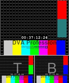
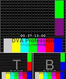
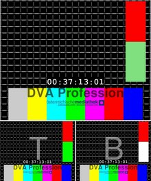
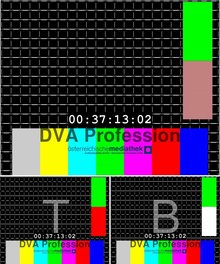
The following image sequence shows the reference frame images, and below them the corresponding fields (marked here with 'T' and 'B' to indicate which is the top- and which is the bottom-field)
|
|
||||
|
There are 2 color rectangles in each field. The upper rectangles of the top- and bottom-field in a frame always have the same color, and the lower rectangles never have the same color if they are in the same frame. Some colors only appear in bottom fields. Now it is necessary to have different color combinations in a short frame sequence to allow the detection of dropped or inserted frames. This frame sequence is simply repeated infinitely within the test video.
Knowing the colors of the first so called "reference frame", makes it even possible to automatically find the position of the first frame of our test-sequence in a recording. Starting at the first reference frame, it is clear which 2 colors per field (=4 colors per frame) are to be expected in all subsequent fields/frames. The timing-analysis-tool simply verifies the accuracy of the recorded reference sequence. Once it encounters a field/frame appearing at the wrong position in time - which means that timing had been tampered with - the analyzer marks that frame position as possibly erroneous, by writing the frame index number into a textfile.
This color sequence developed by us is designed to cope with timing issues of up to 8 fields (or 4 frames), which has so far proven to be sufficient to spot real-life timing issues.
During analysis evaluation, only a small area (16x16 pixel) is extracted from each color rectangle for comparison to speed up the process.
How is the test performed?
- Preparing the onetime prerequisites:
- A specially crafted test video with features necessary for automatic, machine based detection of timing issues, is generated once on a computer as a video file. This video is of course stored in lossless video codec.
- From the digital original version of this test video, a copy is recorded onto a video format which is to be tested (e.g. VHS, DigiBeta, DV, ...). This only has to be done once for each format used later on.
- at least one pass with an accurately timed digital source, in which all devices are connected to a genlock, is recorded. This recording should not require any timing correction, and will therefore give evidence of occuring failures resulting from the environment itself. This step has to be done again when changing common parts in the signal chain (e.g. different cables, different equipment, different capture application, ...)
- The test video is then played back and recorded through the signal chain in question.
- That recording is then processed by DVA Fidelity:
- the result of the automatic evaluation tool is a plain text file containing frame index numbers of images containing errors. (See chapter 3: "Analysis result textfile")
- In order to deal with different kinds of color deviations (e.g. noise, colorspace conversion, etc.), the tolerance level of the evaluation tool can be adjusted to fit the material to be analyzed. This is very important when using analogue signals in the chain - either as carrier (e.g. VHS) or as connection signal (e.g. CVBS).
- In case of timing changes, the analyzer tool re-synchronizes itself onto the video stream. This is necessary to proceed with scanning the video for subsequent issues after a signal deviation has been encountered.
- The analysis result also contains a numeric value for each detected issue, representing the number of pixels deviating from the expected color value. In case of timing issues, this value is always the maximum number of pixels in the reference cutout square (which in our case is 16x16, therefore 256 pixels). This value is influenced by the tolerance adjustment mentioned above.
- The exact kind of incident found during a pass is intentionally not automatically interpreted - all issues are manually sighted by a video operator who intensively examines and investigates the marked frames. Not in all cases does the occurance of a signal deviation indicate a failure. Often it just shows whether, at which time and how a correction of the timing had to be done - as for example by a "time base corrector" (TBC).
- For video that came from a physical carrier (e.g. VHS), there have to be at least two recordings from the same tape over the exact same signal chain in order to distinguish tape (carrier) errors from timing/signal issues during the evaluation of the analysis results. Since they originate from the carrier source, such signal damages will occur in both captured files precisely at the same position. Other issues that appear in just one of the recordings indicate a timing change which is independent from the source material and therefore introduced somewhere within the signal chain used. This dual-pass recording step is also necessary to verify the condition of the physical test-tapes generated at the beginning.
1.2) Explaining the frame/field timing notation
This article contains exact examples of frame/field timing issues, which require a certain notation to easily describe them in a text-based environment. In order to be able to interpret timing-issues mentioned in this article, the reader should be familiar with the notation being used.
It is called "fT/B Notation" and its syntax is described in this section.
Each frame is written in 2 lines. One line per field, where the upper and lower line represent the top/bottom field of the resulting output video. The relation between source- and destination-video is indicated by the number of the frame index in the video-source, and the letters "T" and "B", again representing the top- and bottom-field. The exact frame numbers used are irrelevant, but usually start at 1 (or 2, in case the sequence refers to a frame before that), since it shall only represent the basic concept of a certain incident.
Common example
-
A regular frame at index 1 would be written as:
1T 1B (Top) (Bottom) -
The next frame at index 2 would therefore be written as:
2T 2B - A correct sequence of frames would look like:
Now, if a timing error is present in an output video, where the top- ("T") and bottom-field ("B") are swapped in frame #3, the notation would be:1T 2T 3T ... 20T 1B 2B 3B ... 20B
As you can see, simply the letters "B" and "T" of frame #3 are swapped between upper and lower line.1T 2T 3B 4T 1B 2B 3T 4B
Y/C split example
In some cases, the luminance (Y) and chrominance (C) channels are not treated as a unity, leading to images with Y/C mixed from different fields. The notation is simply expanded by the lowercase letters "y" and "c" and therefore allows to describe luminance and chrominance source/destination deviations in an exact way.-
A regular frame at index 1 would therefore be written as:
1Ty/1Tc 1By/1Bc -
A broken frame at index 2 with its bottom-field chrominance (C) taken from the top-field of frame 1, would be written like this:
-or-2Ty/2Tc 2By/1Tc
In practice, sane frames would be written in regular T/B-Notation and only frames affected by Y/C split properties, would explicitely be written with Y/C split addon information.2T 2By/1Tc -
The above example in a sequence would therefore be:
1T 2Ty/2Tc 3T 1B 2By/1Tc 3B


