2) Detectable issues
2.1) Changing duration
Frame
Field
2.2) Preserving duration
2.3) Other
Y/C split
Rainbow-parade
Genlock verification
RGB mismatch
2) Detectable issues
In the following section, a number of different categories of issues are listed, which can automatically be detected by DVA Fidelity.
With a few exceptions, all issues listed here actually appeared during extensive tests performed on a series of video A/D converter models from different manufacturers. Those that we did not yet encounter in our tests, are marked accordingly. For more details about our A/D converter test series, see: Section 4 - "Converter tests".
However, in order to still provide the reader with information about whether a certain issue is more common to appear on different equipment or not, the listed issues are marked with uppercase letters, where each letter represents a converter device used in our tests.
2.1) Changing duration
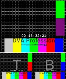
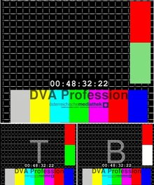
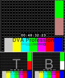
Frame
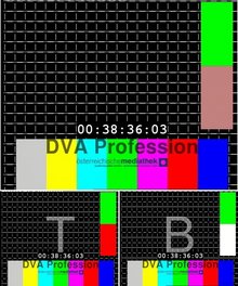
Frame inserted - stretching length
|
frame 1
|
frame 2
|
frame 3
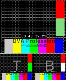
frame_inserted |
frame 4
|
|
Frame dropped – reducing length
|
frame 1

|
frame_dropped |
frame 3

|
frame 4
|
|
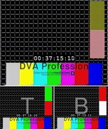
Double field drop – reducing length
|
frame 1

|
frame 2
double_field_drop |
frame 3

|
|
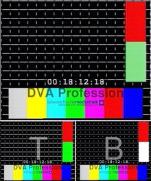
Double field insert – stretching length
Variant 1
|
frame 1
|
frame 2

|
frame 3

double_field_insert |
frame 4

|
|
Variant 2
|
frame 1

|
frame 2

double_field_insert |
frame 3

|
frame 4

|
|
Variant 3
(not found)
Variant 4
(not found)
Field
Field insert
Variant 1
(not found)
Variant 2
(not found)
Field dropped
(not found)
2.2) Preserving duration
Field swap
(not found)
Frame replaced
|
frame 1

|
frame 2

|
frame 3

frame_replaced |
frame 4

|
|
Field replaced
Variant 1
|
frame 1

|
frame 2

field_replaced |
frame 3

|
|
Variant 2
|
frame 1

|
frame 2

field_replaced |
frame 3

|
|
Variant 3
|
frame 1

|
frame 2

field_replaced |
frame 3

|
|
Variant 4
|
frame 1

|
frame 2

field_replaced |
frame 3

|
|
Variant 5
|
frame 1

|
frame 2

field_replaced |
frame 3

|
|
Variant 6
|
frame 1

|
frame 2

field_replaced |
frame 3

|
|
2.3) Other
Y/C split
Timing difference between luminance and chrominance:
Y/C interpolation
(Luminance or chrominance is interpolated between fields)
Chrominance interpolation
Luminance interpolation
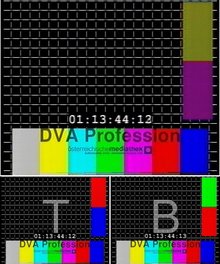
Y/C shift
(Luminance information is correct, but chrominance is taken from the wrong field)
Image interpretation:
The color combination "red/blue" only appears in bottom fields. The grid however belongs to a top field.
(Note: The A/D converter that produced this recording, actually mixes 2 issues in this case: a Y/C split and an inserted field)
|
frame 1
yc_shift |
|
Rainbow-parade
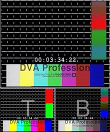
While using a certain VHS player (professional, rack-mountable), we stumbled over color distortions that only affected a single field every few minutes. This is of course just an image quality degradation and no timing issue, but
DVA Fidelity pointed it out, even though it only happend for the duration of a single field.
|
frame 1

|
frame 2
rainbow_parade |
frame 3

|
|
Genlock verification
DVA Fidelity can be used to verify the correct functionality of genlocked equipment, assuring that every equipment in that signal chain is running in sync.
If all video equipment in a signal chain is connected to a generator lock (genlock) clocking signal, no timing correction should be necessary, as each timer of each individual device should be slaved to a common clock. In practice however, it is not always easily noticeable if every connected device is actually complying with the genlock signal, which may cause timing issues that usually pass by unnoticed. This can easily happen due to misconfiguring parameters of devices used in the signal chain, as sophisticated professional equipment allows different genlock modes to be used. Additionally, it can also happen that even with correct settings, a device may be malfunctioning and not synchronizing to the genlock signal correctly.
In both cases, a video operator may be convinced that everything is in order, although the video sent through that signal chain may suffer from unnecessary timing corrections.
We actually had the case with one of our A/D converters, where we figured out that it completely ignored any incoming genlock input as reference signal.
RGB mismatch
When dealing with RGB component signals, it can happen that the color channels are for some reasons not matched correctly, leading to false color display.
Although this might seem trivial to visually spot on the first look, it is still mentioned here, because the correct routing of RGB colors is automatically verified as a side-effect of DVA Fidelity's testing algorithm. For example, the order of the color channels does not always have to be Red-Green-Blue, but can also be BGR, RBG, etc. (especially in the digital domain on a file/codec level). Additionally verifying this might be helpful in environments where multiple RGB component signals are connected using patchbays.


